

商品详情
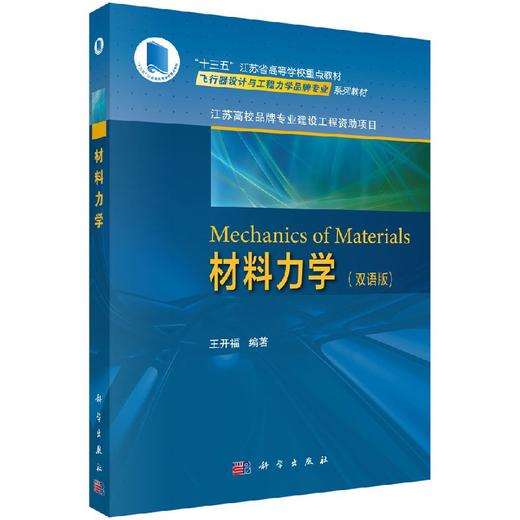
书名:Mechanics of Materials材料力学(双语版)
定价:79.0
ISBN:9787030589361
作者:无
版次:1
出版时间:2018-09
内容提要:
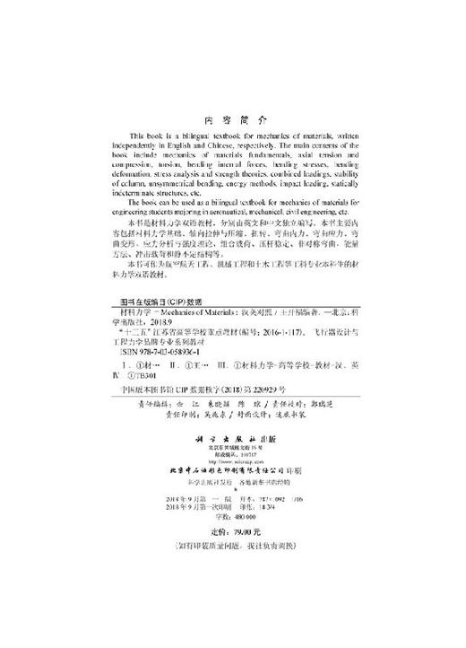
This book is a bilingual textbook for mechanics of materials, written independently in English and Chinese, respectively. The main contents of the book include mechanics of materials fundamentals, axial tension and compression, torsion, bending internal forces, bending stresses, bending deformation, stress analysis and strength theories, combined loadings, stability of column, unsymmetrical bending, energy methods, impact loading, statically indeterminate structures, etc.
本书是材料力学双语教材,分别由英文和中文独立编写。本书主要内容包括材料力学基础、轴向拉伸与压缩、扭转、弯曲内力、弯曲应力、弯曲变形、应力分析与强度理论、组合载荷、压杆稳定、非对称弯曲、能量方法、冲击载荷和静不定结构等。
目录:
Contents
Chapter 1 Mechanics of Materials Fundamentals 1
1.1 External Forces 1
1.2 Internal Forces 2
1.3 Stresses 3
1.4 Strains 7
1.5 Hooke’s Law 9
1.6 Tensile Properties of Low-Carbon Steel 9
1.7 Stress-Strain Curve of Ductile Materials Without Distinct Yield Point 11
1.8 Ductile and Brittle Materials 12
1.9 Properties of Materials in Compression 12
Problems 13
Chapter 2 Axial Tension and Compression 15
2.1 Axial Force 15
2.2 Normal Stress on Cross Section 15
2.3 Normal and Shearing Stresses on Oblique Section 16
2.4 Normal Strain 18
2.5 Tensile and Compressive Deformation 19
2.6 Statically Indeterminate Bar in Tension and Compression 21
2.7 Design of Tensile and Compressive Bar 22
Problems 22
Chapter 3 Torsion 25
3.1 Torsional Moment 25
3.2 Hooke’s Law in Shear 25
3.3 Shearing Stress on Cross Section 26
3.4 Normal and Shearing Stresses on Oblique Section 29
3.5 Angle of Twist 29
3.6 Statically Indeterminate Shaft 31
3.7 Design of Torsional Shaft 31
Problems 32
Chapter 4 Bending Internal Forces 35
4.1 Shearing-Force and Bending-Moment Diagrams 35
4.2 Relations Between Distributed Load, Shearing Force, and Bending Moment 38
4.3 Relations Between Concentrated Load, Shearing Force, and Bending Moment 40
Problems 42
Chapter 5 Bending Stresses 44
5.1 Normal Stresses on Cross Section in Pure Bending 44
5.2 Normal and Shearing Stresses on Cross Section in Transverse-Force Bending 48
5.3 Design of Bending Beam 52
Problems 53
Chapter 6 Bending Deformation 56
6.1 Method of Integration 57
6.2 Method of Superposition 58
6.3 Statically Indeterminate Beam 59
Problems 60
Chapter 7 Stress Analysis and Strength Theories 62
7.1 Stress Transformation 62
7.2 Principal Stresses 64
7.3 Maximum Shearing Stress 66
7.4 Pressure Vessels 67
7.5 Generalized Hooke’s Law 69
7.6 Strength Theories 71
Problems 75
Chapter 8 Combined Loadings 77
8.1 Bar in Eccentric Tension or Compression 77
8.2 I-Beam in Transverse-Force Bending 79
8.3 Beam in Bending and Tension/Compression 82
8.4 Shaft in Torsion and Bending 83
Problems 86
Chapter 9 Stability of Column 88
9.1 Critical Load of Long Column with Pin Supports 88
9.2 Critical Load of Long Column with Other Supports 89
9.3 Critical Stress of Long Column 90
9.4 Critical Stress of Intermediate Column 91
9.5 Design of Column 92
Problems 94
Chapter 10 Unsymmetrical Bending 96
10.1 Unsymmetrical Pure Bending 96
10.2 Unsymmetrical Transverse-Force Bending 99
Problems 104
Chapter 11 Energy Methods 106
11.1 External Work 106
11.2 Stain-Energy Density 107
11.3 Strain Energy 108
11.4 Principle of Work and Energy 111
11.5 Reciprocal Theorem 112
11.6 Castigliano’s Theorem 113
11.7 Principle of Virtual Work 116
11.8 Unit Load Method 118
11.9 Applications of Energy Methods 120
Problems 121
Chapter 12 Impact Loading 125
12.1 Vertical Impact 125
12.2 Horizontal Impact 127
Problems 129
Chapter 13 Statically Indeterminate Structures 131
13.1 Static Indeterminacy 131
13.2 Force Method for Analysis of Statically Indeterminate Structures 132
13.3 Force Method for Analysis of Symmetrical Statically-Indeterminate Structures 137
Problems 139
Appendix I Properties of Area 143
I.1 First Moment (Static Moment) 143
I.2 Moment of Inertia and Polar Moment of Inertia 144
I.3 Radius of Gyration and Polar Radius of Gyration 144
I.4 Product of Inertia 145
I.5 Parallel-Axis Theorem 145
I.6 Properties of Commonly-Used Areas 146
Appendix II Shape Steels 147
II.1 I-Steel 147
II.2 Channel Steel 148
II.3 Equal Angle Steel 149
II.4 Unequal Angle Steel 151
Appendix III Deflection Curves 154
References 155
目录
第1章 材料力学基础 156
1.1 外力 156
1.2 内力 157
1.3 应力 158
1.4 应变 160
1.5 胡克定律 162
1.6 低碳钢拉伸性能 162
1.7 无明显屈服点塑性材料的应力应变曲线 164
1.8 塑性材料和脆性材料 165
1.9 材料压缩性能 165
*题 165
第2章 轴向拉伸与压缩 167
2.1 轴力 167
2.2 横截面正应力 167
2.3 斜截面正应力和剪应力 168
2.4 线应变 170
2.5 拉压变形 171
2.6 静不定拉压杆 172
2.7 拉压杆设计 173
*题 173
第3章 扭转 176
3.1 扭矩 176
3.2 剪切胡克定律 176
3.3 横截面剪应力 177
3.4 斜截面正应力和剪应力 179
3.5 扭转角 180
3.6 静不定轴 180
3.7 扭转轴设计 181
*题 182
第4章 弯曲内力 184
4.1 剪力图和弯矩图 184
4.2 分布载荷、剪力和弯矩之间的关系 186
4.3 集中载荷、剪力和弯矩之间的关系 188
*题 189
第5章 弯曲应力 191
5.1 纯弯曲横截面正应力 191
5.2 横力弯曲横截面正应力和剪应力 194
5.3 弯曲梁设计 197
*题 198
第6章 弯曲变形 201
6.1 积分法 202
6.2 叠加法 203
6.3 静不定梁 203
*题 204
第7章 应力分析与强度理论 206
7.1 应力变换 206
7.2 主应力 208
7.3 *大剪应力 209
7.4 压力容器 211
7.5 广义胡克定律 212
7.6 强度理论 214
*题 217
第8章 组合载荷 218
8.1 偏心拉压杆 218
8.2 横力弯曲工字梁 219
8.3 拉压弯曲梁 221
8.4 弯曲扭转轴 223
*题 225
第9章 压杆稳定 227
9.1 两端铰支细长压杆临界载荷 227
9.2 其他支撑细长压杆临界载荷 228
9.3 细长压杆临界应力 228
9.4 中长压杆临界应力 229
9.5 压杆设计 230
*题 232
第10章 非对称弯曲 233
10.1 非对称纯弯曲 233
10.2 非对称横力弯曲 236
*题 239
第11章 能量方法 241
11.1 外功 241
11.2 应变能密度 242
11.3 应变能 243
11.4 功能原理 245
11.5 互等定理 246
11.6 卡氏定理 247
11.7 虚功原理 250
11.8 单位载荷法 251
11.9 能量方法应用 252
*题 254
第12章 冲击载荷 257
12.1 垂直冲击 257
12.2 水平冲击 259
*题 261
第13章 静不定结构 263
13.1 静不定 263
13.2 力法分析静不定结构 263
13.3 力法分析对称静不定结构 268
*题 270
附录I 截面性质 273
I.1 静矩 273
I.2 惯性矩与极惯性矩 274
I.3 惯性半径与极惯性半径 274
I.4 惯性积 275
I.5 平行移轴定理 275
I.6 常用截面几何性质 276
附录II 型钢 277
II.1 工字钢 277
II.2 槽钢 278
II.3 等边角钢 279
II.4 不等边角钢 281
附录III 挠度曲线 284
参考文献 285
在线试读:
Chapter 1 Mechanics of Materials Fundamentals
In theoretical mechanics, bodies are assumed to be perfectly rigid.The deformations of bodies are important, however, as far as the resistance of the structures and machines to failure is concerned.Therefore, the bodies in mechanics of materials will no longer be assumed to be perfectly rigid as considered in theoretical mechanics.
Mechanics of materials studies the ability of structures and machines to resist failure, and mainly involves the following tasks: ① strength, i.e., the ability of members to support a specified load without experiencing excessive stresses; ② rigidity, i.e., the ability of members to support a specified load without undergoing unacceptable deformations; ③ stability, i.e., the ability of members to support a specified axial compressive load without causing a sudden lateral deflection.
Any material dealt with in mechanics of materials is assumed to be: ① continuous, i.e., the material consists of a continuous distribution of matter without voids; ② homogeneous, i.e., the material possesses the same mechanical properties at all points in the matter; ③ isotropic, i.e., the material has the same mechanical properties in all directions at any one point of the matter.
The strength and rigidity of a material depend on its abilities to support a specified load without experiencing both excessive stresses and unacceptable deformations.These abilities are inherent in the material itself and must be determined by experimental methods.One of the most important tests to determine the mechanical properties of a material is the tensile or compressive test.This test is often used to determine the stress-strain relation of the material used.
1.1 External Forces
Any external force applied to a body can be classified as either a surface force or a body force.
1.Surface Force
An external force that is applied to the surface of a body is called a surface force.
If the surface force is distributed over a finite area of the body, it is said to be a distributed load on a surface, Fig.1.1(a).If the surface force is applied along a narrow area, this force is defined as a distributed load along a line, Fig.1.1(b).If the area subjected to a surface force is very small, compared with the surface area of the body, then this surface force can be regarded as a concentrated load, Fig.1.1(c).
Fig.1.1
2.Body Force
An external force that is applied to every point within a body is called a body force.A gravitational force is an excellent example of the body force since it acts upon each of the particles forming the body.
1.2 Internal Forces
When various external loads are applied to a member, the corresponding distributed internal forces will be developed at any point within the member.The distributed internal forces on any section within the member can be determined by using the method of sections.
We imagine to use a plane , Fig.1.2(a), to section the member where the distributed internal forces need to be determined.For determination of the distributed internal forces on the cut plane, the portion of the member to the right of the cut plane is removed, and it is replaced by the distributed internal forces acting on the left portion, Fig.1.2(b).
Fig.1.2
For equilibrium of the remaining portion of the member, the distributed internal forces can be determined by using the equations of static equilibrium.Although the exact distribution of internal forces may be unknown, we can use the equations of static equilibrium to relate the applied external loads to the resultant force R and resultant couple MO about point O on the cut plane, which are caused by the distributed internal forces, Fig.1.3(a).
Fig.1.3
Generally speaking, the resultant force R and resultant couple MO have arbitrary directions,neither perpendicular nor parallel to the cut plane.However,we can resolve the resultant force and couple into six components, respectively along the x, y, and z axes, Fig.1.3(b).
(1) Axial force.The normal component, along the x direction, of the resultant force is called the axial force (normal force), N.It is developed when the external loads tend to pull or push the two segments of the member.
(2) Shearing force.The tangential components, respectively along the y and z directions, of the resultant force are regarded as the shearing forces, denoted by Vy and Vz, which are developed when the external loads tend to cause the two segments of the member to slide over one another.
(3) Torsional moment.The normal component, rotating about the x axis, of the resultant couple is called the torsional moment (twisting moment, or torque), T, and developed when the external loads tend to twist one segment of the member with respect to the other.
(4) Bending moment.The tangential components of the resultant couple tend to bend the member about the y and z axes, respectively.These two components, My and Mz, rotating about the y and z axes respectively, are called the bending moments.
1.3 Stresses
The distributed internal forces are developed at any point within the member subjected to external loads.To define the stress at a given point P of the section, Fig.1.4(a), we consider a small area A containing P and assume that the resultant force is F on the area A.In general, the force F has a unique direction at a given point on the section and can be resolved into three components N,Vy and Vz respectively along the x, y, and z axes, Fig.1.4(b).N is the normal component perpendicular to the area A,Vy and Vz are the two tangential components within the area A.
Fig.1.4
1.Normal Stress
The intensity of the normal force, the normal force per unit area, acting normal to the area is defined as the normal stress, denoted by.The normal stress at the given point P on the section of the member, Fig.1.5, can be expressed as
(1.1)
where x is perpendicular to the section and the subscript represents the outward normal of the section and the direction of the normal stress.A positive sign is usually used to indicate a tensile stress and a negative sign to indicate a compressive stress.From SI units, with N expressed in N and A in m2, the normal stress x is expressed in Pascal (Pa).
2.Shearing Stress
The intensity of the tangential force, the tangential force per unit area, acting tangent to the area is called the shearing stress, denoted by.The two shearing stress components at the given point P on the section of the member, Fig.1.6, can be written, respectively, as
(1.2)
where xy and xz lie in the section.Two subscripts are used for the shearing stress components:the first represents the direction of the outward normal line of the section; and the second indicates the direction of the shearing stress.In SI units, the shearing stresses xy and xz are also measured in Pa.
Fig.1.5
Fig.1.6
In order to show how shearing stresses develop,we will consider a member subjected to two transverse forces of magnitude F, Fig.1.7(a).
Sectioning the member at CC between the points of application of the two forces, and considering the equilibrium of the left portion, Fig.1.7(b), we conclude that distributed internal forces must exist in the cross section.The resultant of these distributed internal forces is called direct shearing force, denoted by V.Dividing the direct shearing force V in the cross section by the area A of the cross section, we obtain the direct shearing stress in the section.Denoting the direct shearing stress by the letter, we have
(1.3)
We should note that the value obtained is an average value of the shearing stress over the entire section.
Direct shearing stresses are commonly found in bolts, pins, and rivets used to connect various structural members and machine components.Consider the two plates, which are connected by a bolt, Fig.1.8(a).If the plates are subjected to two tension forces of magnitude F,a direct shearing stress will develop in the section of bolt corresponding to the contacting surface of the plates.Drawing the diagram of the bolt located below the contacting surface, Fig.1.8(b),we conclude that the direct shearing stress in the section is equal to V /A.
Fig.1.7
Fig.1.8
Example 1.1 A load F is applied to a steel rod supported as shown in Fig.1.9(a) by a plate into which a 15 mm diameter hole has been drilled.Knowing that the shearing stress must not exceed 120 MPa in the steel, determine the largest load Fmax which may be applied to the rod.
Solution The shearing plane is a cylindrical surface, Fig.1.9(b), and its shearing area is equal to A πdt .Since the maximum shearing stress max 120 MPa, then the largest load Fmax can, from Eq.(1.3), be obtained by
Fig.1.9
3.Bearing Stress
Bolts, pins, and rivets create stresses on the bearing surface of the members they connect.Consider two plates connected by a bolt, Fig.1.10(a).The bolt exerts on the upper plate a force Fbs, Fig.1.10(b), equal and opposite to the force F'bs exerted by the upper plate on the bolt, Fig.1.10(c).The force Fbs exerted by the bolt represents the resultant of distributed forces on the inside surface of a half-cylinder.
Since the distribution of forces on the contacting surface of the members is quite complicated, the average value of the stress, obtained by dividing the resultant Fbs by the projected area Abs of the bolt on the plate section,is regarded as the bearing stress bs.Since this projected area Abs is equal to td, where t is the plate thickness and d is the diameter of the bolt, we have
(1.4)
Example 1.2 A load F is applied to a steel rod supported as shown in Fig.1.11(a) by a plate into which a 15 mm diameter hole has been drilled.Knowing that the bearing stress of the steel must not exceed 150 MPa, determine the largest load Fmax which may be applied to the rod.
Fig.1.10 Fig.1.11
定价:79.0
ISBN:9787030589361
作者:无
版次:1
出版时间:2018-09
内容提要:
This book is a bilingual textbook for mechanics of materials, written independently in English and Chinese, respectively. The main contents of the book include mechanics of materials fundamentals, axial tension and compression, torsion, bending internal forces, bending stresses, bending deformation, stress analysis and strength theories, combined loadings, stability of column, unsymmetrical bending, energy methods, impact loading, statically indeterminate structures, etc.
本书是材料力学双语教材,分别由英文和中文独立编写。本书主要内容包括材料力学基础、轴向拉伸与压缩、扭转、弯曲内力、弯曲应力、弯曲变形、应力分析与强度理论、组合载荷、压杆稳定、非对称弯曲、能量方法、冲击载荷和静不定结构等。
目录:
Contents
Chapter 1 Mechanics of Materials Fundamentals 1
1.1 External Forces 1
1.2 Internal Forces 2
1.3 Stresses 3
1.4 Strains 7
1.5 Hooke’s Law 9
1.6 Tensile Properties of Low-Carbon Steel 9
1.7 Stress-Strain Curve of Ductile Materials Without Distinct Yield Point 11
1.8 Ductile and Brittle Materials 12
1.9 Properties of Materials in Compression 12
Problems 13
Chapter 2 Axial Tension and Compression 15
2.1 Axial Force 15
2.2 Normal Stress on Cross Section 15
2.3 Normal and Shearing Stresses on Oblique Section 16
2.4 Normal Strain 18
2.5 Tensile and Compressive Deformation 19
2.6 Statically Indeterminate Bar in Tension and Compression 21
2.7 Design of Tensile and Compressive Bar 22
Problems 22
Chapter 3 Torsion 25
3.1 Torsional Moment 25
3.2 Hooke’s Law in Shear 25
3.3 Shearing Stress on Cross Section 26
3.4 Normal and Shearing Stresses on Oblique Section 29
3.5 Angle of Twist 29
3.6 Statically Indeterminate Shaft 31
3.7 Design of Torsional Shaft 31
Problems 32
Chapter 4 Bending Internal Forces 35
4.1 Shearing-Force and Bending-Moment Diagrams 35
4.2 Relations Between Distributed Load, Shearing Force, and Bending Moment 38
4.3 Relations Between Concentrated Load, Shearing Force, and Bending Moment 40
Problems 42
Chapter 5 Bending Stresses 44
5.1 Normal Stresses on Cross Section in Pure Bending 44
5.2 Normal and Shearing Stresses on Cross Section in Transverse-Force Bending 48
5.3 Design of Bending Beam 52
Problems 53
Chapter 6 Bending Deformation 56
6.1 Method of Integration 57
6.2 Method of Superposition 58
6.3 Statically Indeterminate Beam 59
Problems 60
Chapter 7 Stress Analysis and Strength Theories 62
7.1 Stress Transformation 62
7.2 Principal Stresses 64
7.3 Maximum Shearing Stress 66
7.4 Pressure Vessels 67
7.5 Generalized Hooke’s Law 69
7.6 Strength Theories 71
Problems 75
Chapter 8 Combined Loadings 77
8.1 Bar in Eccentric Tension or Compression 77
8.2 I-Beam in Transverse-Force Bending 79
8.3 Beam in Bending and Tension/Compression 82
8.4 Shaft in Torsion and Bending 83
Problems 86
Chapter 9 Stability of Column 88
9.1 Critical Load of Long Column with Pin Supports 88
9.2 Critical Load of Long Column with Other Supports 89
9.3 Critical Stress of Long Column 90
9.4 Critical Stress of Intermediate Column 91
9.5 Design of Column 92
Problems 94
Chapter 10 Unsymmetrical Bending 96
10.1 Unsymmetrical Pure Bending 96
10.2 Unsymmetrical Transverse-Force Bending 99
Problems 104
Chapter 11 Energy Methods 106
11.1 External Work 106
11.2 Stain-Energy Density 107
11.3 Strain Energy 108
11.4 Principle of Work and Energy 111
11.5 Reciprocal Theorem 112
11.6 Castigliano’s Theorem 113
11.7 Principle of Virtual Work 116
11.8 Unit Load Method 118
11.9 Applications of Energy Methods 120
Problems 121
Chapter 12 Impact Loading 125
12.1 Vertical Impact 125
12.2 Horizontal Impact 127
Problems 129
Chapter 13 Statically Indeterminate Structures 131
13.1 Static Indeterminacy 131
13.2 Force Method for Analysis of Statically Indeterminate Structures 132
13.3 Force Method for Analysis of Symmetrical Statically-Indeterminate Structures 137
Problems 139
Appendix I Properties of Area 143
I.1 First Moment (Static Moment) 143
I.2 Moment of Inertia and Polar Moment of Inertia 144
I.3 Radius of Gyration and Polar Radius of Gyration 144
I.4 Product of Inertia 145
I.5 Parallel-Axis Theorem 145
I.6 Properties of Commonly-Used Areas 146
Appendix II Shape Steels 147
II.1 I-Steel 147
II.2 Channel Steel 148
II.3 Equal Angle Steel 149
II.4 Unequal Angle Steel 151
Appendix III Deflection Curves 154
References 155
目录
第1章 材料力学基础 156
1.1 外力 156
1.2 内力 157
1.3 应力 158
1.4 应变 160
1.5 胡克定律 162
1.6 低碳钢拉伸性能 162
1.7 无明显屈服点塑性材料的应力应变曲线 164
1.8 塑性材料和脆性材料 165
1.9 材料压缩性能 165
*题 165
第2章 轴向拉伸与压缩 167
2.1 轴力 167
2.2 横截面正应力 167
2.3 斜截面正应力和剪应力 168
2.4 线应变 170
2.5 拉压变形 171
2.6 静不定拉压杆 172
2.7 拉压杆设计 173
*题 173
第3章 扭转 176
3.1 扭矩 176
3.2 剪切胡克定律 176
3.3 横截面剪应力 177
3.4 斜截面正应力和剪应力 179
3.5 扭转角 180
3.6 静不定轴 180
3.7 扭转轴设计 181
*题 182
第4章 弯曲内力 184
4.1 剪力图和弯矩图 184
4.2 分布载荷、剪力和弯矩之间的关系 186
4.3 集中载荷、剪力和弯矩之间的关系 188
*题 189
第5章 弯曲应力 191
5.1 纯弯曲横截面正应力 191
5.2 横力弯曲横截面正应力和剪应力 194
5.3 弯曲梁设计 197
*题 198
第6章 弯曲变形 201
6.1 积分法 202
6.2 叠加法 203
6.3 静不定梁 203
*题 204
第7章 应力分析与强度理论 206
7.1 应力变换 206
7.2 主应力 208
7.3 *大剪应力 209
7.4 压力容器 211
7.5 广义胡克定律 212
7.6 强度理论 214
*题 217
第8章 组合载荷 218
8.1 偏心拉压杆 218
8.2 横力弯曲工字梁 219
8.3 拉压弯曲梁 221
8.4 弯曲扭转轴 223
*题 225
第9章 压杆稳定 227
9.1 两端铰支细长压杆临界载荷 227
9.2 其他支撑细长压杆临界载荷 228
9.3 细长压杆临界应力 228
9.4 中长压杆临界应力 229
9.5 压杆设计 230
*题 232
第10章 非对称弯曲 233
10.1 非对称纯弯曲 233
10.2 非对称横力弯曲 236
*题 239
第11章 能量方法 241
11.1 外功 241
11.2 应变能密度 242
11.3 应变能 243
11.4 功能原理 245
11.5 互等定理 246
11.6 卡氏定理 247
11.7 虚功原理 250
11.8 单位载荷法 251
11.9 能量方法应用 252
*题 254
第12章 冲击载荷 257
12.1 垂直冲击 257
12.2 水平冲击 259
*题 261
第13章 静不定结构 263
13.1 静不定 263
13.2 力法分析静不定结构 263
13.3 力法分析对称静不定结构 268
*题 270
附录I 截面性质 273
I.1 静矩 273
I.2 惯性矩与极惯性矩 274
I.3 惯性半径与极惯性半径 274
I.4 惯性积 275
I.5 平行移轴定理 275
I.6 常用截面几何性质 276
附录II 型钢 277
II.1 工字钢 277
II.2 槽钢 278
II.3 等边角钢 279
II.4 不等边角钢 281
附录III 挠度曲线 284
参考文献 285
在线试读:
Chapter 1 Mechanics of Materials Fundamentals
In theoretical mechanics, bodies are assumed to be perfectly rigid.The deformations of bodies are important, however, as far as the resistance of the structures and machines to failure is concerned.Therefore, the bodies in mechanics of materials will no longer be assumed to be perfectly rigid as considered in theoretical mechanics.
Mechanics of materials studies the ability of structures and machines to resist failure, and mainly involves the following tasks: ① strength, i.e., the ability of members to support a specified load without experiencing excessive stresses; ② rigidity, i.e., the ability of members to support a specified load without undergoing unacceptable deformations; ③ stability, i.e., the ability of members to support a specified axial compressive load without causing a sudden lateral deflection.
Any material dealt with in mechanics of materials is assumed to be: ① continuous, i.e., the material consists of a continuous distribution of matter without voids; ② homogeneous, i.e., the material possesses the same mechanical properties at all points in the matter; ③ isotropic, i.e., the material has the same mechanical properties in all directions at any one point of the matter.
The strength and rigidity of a material depend on its abilities to support a specified load without experiencing both excessive stresses and unacceptable deformations.These abilities are inherent in the material itself and must be determined by experimental methods.One of the most important tests to determine the mechanical properties of a material is the tensile or compressive test.This test is often used to determine the stress-strain relation of the material used.
1.1 External Forces
Any external force applied to a body can be classified as either a surface force or a body force.
1.Surface Force
An external force that is applied to the surface of a body is called a surface force.
If the surface force is distributed over a finite area of the body, it is said to be a distributed load on a surface, Fig.1.1(a).If the surface force is applied along a narrow area, this force is defined as a distributed load along a line, Fig.1.1(b).If the area subjected to a surface force is very small, compared with the surface area of the body, then this surface force can be regarded as a concentrated load, Fig.1.1(c).
Fig.1.1
2.Body Force
An external force that is applied to every point within a body is called a body force.A gravitational force is an excellent example of the body force since it acts upon each of the particles forming the body.
1.2 Internal Forces
When various external loads are applied to a member, the corresponding distributed internal forces will be developed at any point within the member.The distributed internal forces on any section within the member can be determined by using the method of sections.
We imagine to use a plane , Fig.1.2(a), to section the member where the distributed internal forces need to be determined.For determination of the distributed internal forces on the cut plane, the portion of the member to the right of the cut plane is removed, and it is replaced by the distributed internal forces acting on the left portion, Fig.1.2(b).
Fig.1.2
For equilibrium of the remaining portion of the member, the distributed internal forces can be determined by using the equations of static equilibrium.Although the exact distribution of internal forces may be unknown, we can use the equations of static equilibrium to relate the applied external loads to the resultant force R and resultant couple MO about point O on the cut plane, which are caused by the distributed internal forces, Fig.1.3(a).
Fig.1.3
Generally speaking, the resultant force R and resultant couple MO have arbitrary directions,neither perpendicular nor parallel to the cut plane.However,we can resolve the resultant force and couple into six components, respectively along the x, y, and z axes, Fig.1.3(b).
(1) Axial force.The normal component, along the x direction, of the resultant force is called the axial force (normal force), N.It is developed when the external loads tend to pull or push the two segments of the member.
(2) Shearing force.The tangential components, respectively along the y and z directions, of the resultant force are regarded as the shearing forces, denoted by Vy and Vz, which are developed when the external loads tend to cause the two segments of the member to slide over one another.
(3) Torsional moment.The normal component, rotating about the x axis, of the resultant couple is called the torsional moment (twisting moment, or torque), T, and developed when the external loads tend to twist one segment of the member with respect to the other.
(4) Bending moment.The tangential components of the resultant couple tend to bend the member about the y and z axes, respectively.These two components, My and Mz, rotating about the y and z axes respectively, are called the bending moments.
1.3 Stresses
The distributed internal forces are developed at any point within the member subjected to external loads.To define the stress at a given point P of the section, Fig.1.4(a), we consider a small area A containing P and assume that the resultant force is F on the area A.In general, the force F has a unique direction at a given point on the section and can be resolved into three components N,Vy and Vz respectively along the x, y, and z axes, Fig.1.4(b).N is the normal component perpendicular to the area A,Vy and Vz are the two tangential components within the area A.
Fig.1.4
1.Normal Stress
The intensity of the normal force, the normal force per unit area, acting normal to the area is defined as the normal stress, denoted by.The normal stress at the given point P on the section of the member, Fig.1.5, can be expressed as
(1.1)
where x is perpendicular to the section and the subscript represents the outward normal of the section and the direction of the normal stress.A positive sign is usually used to indicate a tensile stress and a negative sign to indicate a compressive stress.From SI units, with N expressed in N and A in m2, the normal stress x is expressed in Pascal (Pa).
2.Shearing Stress
The intensity of the tangential force, the tangential force per unit area, acting tangent to the area is called the shearing stress, denoted by.The two shearing stress components at the given point P on the section of the member, Fig.1.6, can be written, respectively, as
(1.2)
where xy and xz lie in the section.Two subscripts are used for the shearing stress components:the first represents the direction of the outward normal line of the section; and the second indicates the direction of the shearing stress.In SI units, the shearing stresses xy and xz are also measured in Pa.
Fig.1.5
Fig.1.6
In order to show how shearing stresses develop,we will consider a member subjected to two transverse forces of magnitude F, Fig.1.7(a).
Sectioning the member at CC between the points of application of the two forces, and considering the equilibrium of the left portion, Fig.1.7(b), we conclude that distributed internal forces must exist in the cross section.The resultant of these distributed internal forces is called direct shearing force, denoted by V.Dividing the direct shearing force V in the cross section by the area A of the cross section, we obtain the direct shearing stress in the section.Denoting the direct shearing stress by the letter, we have
(1.3)
We should note that the value obtained is an average value of the shearing stress over the entire section.
Direct shearing stresses are commonly found in bolts, pins, and rivets used to connect various structural members and machine components.Consider the two plates, which are connected by a bolt, Fig.1.8(a).If the plates are subjected to two tension forces of magnitude F,a direct shearing stress will develop in the section of bolt corresponding to the contacting surface of the plates.Drawing the diagram of the bolt located below the contacting surface, Fig.1.8(b),we conclude that the direct shearing stress in the section is equal to V /A.
Fig.1.7
Fig.1.8
Example 1.1 A load F is applied to a steel rod supported as shown in Fig.1.9(a) by a plate into which a 15 mm diameter hole has been drilled.Knowing that the shearing stress must not exceed 120 MPa in the steel, determine the largest load Fmax which may be applied to the rod.
Solution The shearing plane is a cylindrical surface, Fig.1.9(b), and its shearing area is equal to A πdt .Since the maximum shearing stress max 120 MPa, then the largest load Fmax can, from Eq.(1.3), be obtained by
Fig.1.9
3.Bearing Stress
Bolts, pins, and rivets create stresses on the bearing surface of the members they connect.Consider two plates connected by a bolt, Fig.1.10(a).The bolt exerts on the upper plate a force Fbs, Fig.1.10(b), equal and opposite to the force F'bs exerted by the upper plate on the bolt, Fig.1.10(c).The force Fbs exerted by the bolt represents the resultant of distributed forces on the inside surface of a half-cylinder.
Since the distribution of forces on the contacting surface of the members is quite complicated, the average value of the stress, obtained by dividing the resultant Fbs by the projected area Abs of the bolt on the plate section,is regarded as the bearing stress bs.Since this projected area Abs is equal to td, where t is the plate thickness and d is the diameter of the bolt, we have
(1.4)
Example 1.2 A load F is applied to a steel rod supported as shown in Fig.1.11(a) by a plate into which a 15 mm diameter hole has been drilled.Knowing that the bearing stress of the steel must not exceed 150 MPa, determine the largest load Fmax which may be applied to the rod.
Fig.1.10 Fig.1.11